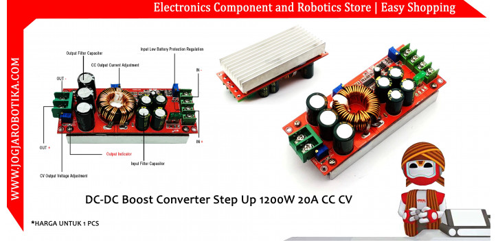
DC-DC Boost Converter Step Up 1200W 20A CC CV
Power description: Because the input current of this power supply is as large as 20A. The output power is related to the input voltage. The higher the input voltage, the greater the power. For example, the input 12V*20A power is 240W. The input 24V*20A is 480W. At this time, it is high power. Due to the limited heat dissipation area, please add a 12V fan to dissipate heat when the input voltage exceeds 10A or the output current reaches 10.
Module parameters:
- Module model: SZ-BT07CCCV-A
- Module name: 1200 W boost constant current module
- Module nature: non-isolated boost module (BOOST)
- Input voltage: DC 10-60V (input 10-60V directly without jumper cap to select voltage)
- Input Current: 2 0A (MAX) exceeds 15A please add cooling fan (cooling fan plus the input current when the input voltage can reach 12-24V 25A)
- Static working current: 15mA (when 12V rises to 20V, the higher the output voltage, the static current will increase)
- Output voltage: 12-80V continuously adjustable.
- Output current: 18 A MAX Please strengthen heat dissipation if it exceeds 10A (related to the input and output pressure difference, the larger the pressure difference, the smaller the output current)
- Constant current range: 0.5-18A (+/-0.3A)
- Input anti-reverse: There (150A is a power MOS Counter)
- Low Voltage Protection: There (9-50V adjustable)
- Operating temperature: - 40 to + 85 degrees (ambient temperature is too high, please enhance heat dissipation)
- Working frequency: 150KHz
- Conversion efficiency: 92% (Efficiency is related to input, output voltage, current, pressure difference. Small pressure difference, high efficiency)
- Input overcurrent protection: Yes (input over 25A, automatic protection, power supply does not boost)
- Short circuit protection: There is (input 30A fuse) double short circuit protection, which is safer to use.
- Input reverse connection protection: Yes (150A power MOS tube is anti-reverse. It can be reversed for a long time )
- Installation method: 4 3mm copper pillars
- Wiring mode: terminal block (please use high-current pure copper wire)
- Module size: length 130mm width 52mm height 53mm
- Module weight : 300 grams
Output power: = input voltage*20A, such as: input 12V*20A=240W when input 12V, the high power is 240W
Input voltage*20A such as: input 24V*20A=480W, that is, when input 24V, the power is 480W
Note: The high power is 240W when the input is 12V, the high power is 480W when the input is 24V, and the high power is 720W when the input is 36V
The power supply material is very fierce. The input uses 4 63V/470UF high-frequency low-resistance electrolytic capacitors, and the output 3 100V/470UF electrolytic capacitors. The 33MM ultra-high-power iron-silicon-aluminum magnetic ring is wound with three 1.2MM pure copper wires in parallel to prevent over-temperature magnetic saturation under high current conditions. Use a 116MM*58MM*14MM aluminum radiator to dissipate heat. And the heat sink has 5015 fan (5MM*5MM*15MM) mounting holes; the output voltage and current of the imported power management chip are continuously adjustable. More importantly, the price is not expensive. There is no such thing as a second Taobao.
Output voltage/output current regulation/input low battery protection regulation
Voltage adjustment: Use a flat-blade screwdriver to adjust the output terminal "V-ADJ" potentiometer (marked in the figure above) clockwise to increase and counterclockwise to decrease) when the power is turned on and there is no load. Due to the large output capacitance, The response will be slower when the output voltage is adjusted from a high voltage to a low voltage. The adjustment range of the instrument is smaller.
Current regulation: inverseclockwise tune "A-ADJ" circle potentiometer 30, the output current is set to smaller, connected to the LED, clockwise tune "A-ADJ" potentiometer to your desired current. For battery charging, after the battery is discharged, connect to the output and adjust RV2 to the current you need. When charging, you must use the discharged battery to adjust it, because the battery has more power , The smaller the charging current.
Pay special attention to:
Never use a short-circuit output method to adjust the current. The circuit structure of the boost module cannot be adjusted by a short-circuit method.
Input low battery protection adjustment: Low battery protection is mainly aimed at preventing battery over-discharge when the input power is a battery, and the battery voltage is too low to damage the power module and battery. For example, set 12V battery low battery protection. Connect a 10V voltage to the input terminal of the power module and use a flat-blade screwdriver to adjust RV1 (clockwise protection voltage value increase, counterclockwise protection voltage decrease) until the UVLO light is on. At this time, the low battery protection voltage is 10V. The power module does not rise when the voltage drops to 10V (the input voltage is equal to the output voltage) when using the boost power supply, the following points should be paid attention to:
1 The voltage of the input power supply must be above 10V.
2 When using a switching power supply as the input power supply, first connect the input power supply and adjust the voltage when there is no load. Then go to the load. (It must be ensured that the switching power supply is always working), or first adjust the voltage without load, then disconnect the switching power supply and then connect the load. Switch on the switching power supply and the power supply module when the switching power supply is turned on. (Because the switching power supply has a climbing time when it is turned on. When the voltage is lower than 10V, the chip is not working. It is easy to break down the MOS tube.
3 When used in constant current mode with constant voltage, make sure that the constant voltage must be higher than the input voltage. (For example, the input voltage of the power supply is 12V and the no-load output voltage is 15V. Then connect a 3.2V LED light. This situation is not allowed. It is necessary to connect 4 LED lights in series)
Application range:
1. DIY a regulated power supply, input 12V, output can be adjusted from 12-80V.
2. To supply power to your electronic equipment, you can set the output value according to your system voltage.
3. As a vehicle power supply, power your laptop, PDA or various digital products.
4. DIY a high-power notebook mobile power supply: equipped with a large-capacity 12V lithium battery pack, so that your books can be bright wherever you go.
5. The solar panel stabilizes the voltage.
6. Charging batteries, lithium batteries, etc.
7. Drive high-power LED lights.


